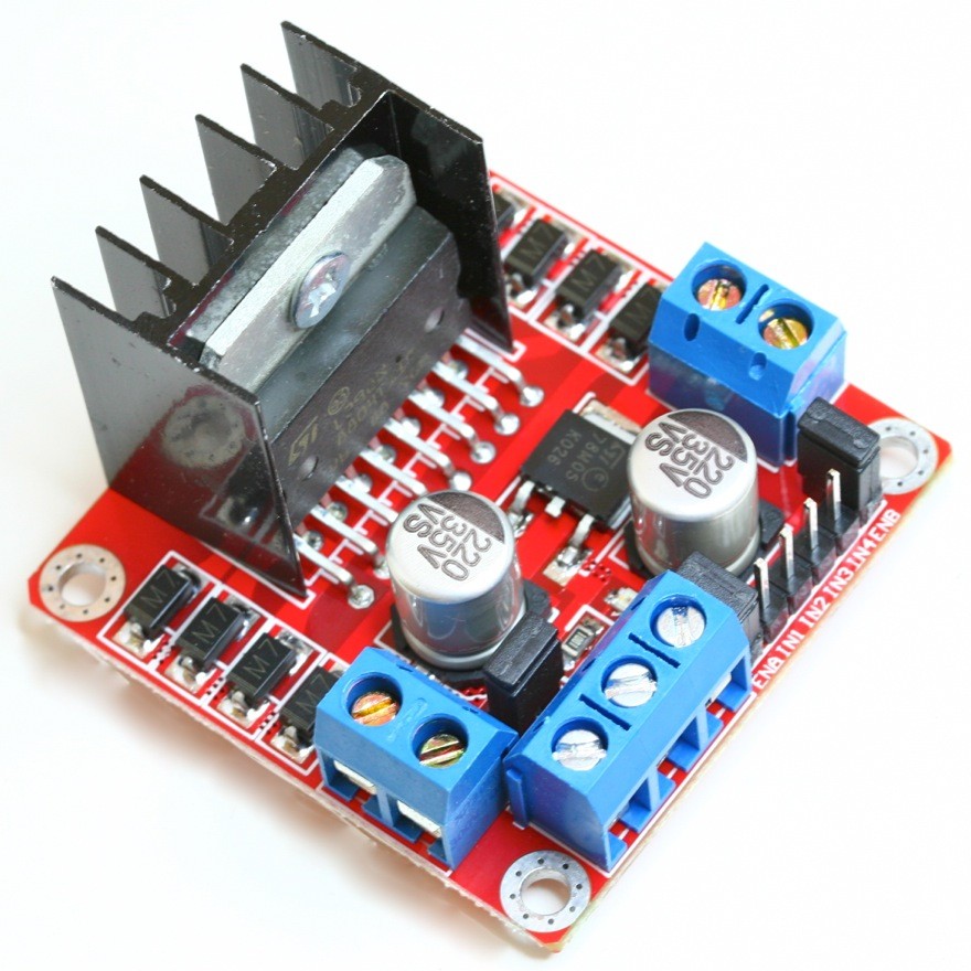
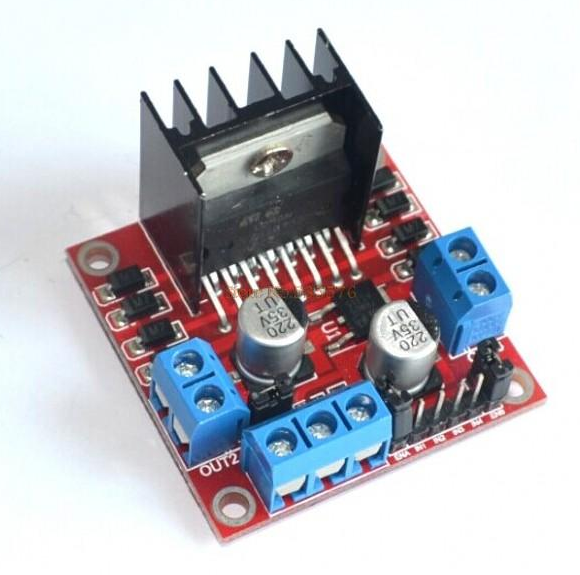
Description
How it works:
An H-Bridge is a circuit that can drive a current in either polarity and be controlled by *Pulse Width Modulation (PWM).
* Pulse Width Modulation is a means in controlling the duration of an electronic pulse. In motors try to imagine the brush as a water wheel and electrons as a the flowing droplets of water. The voltage would be the water flowing over the wheel at a constant rate, the more water flowing the higher the voltage. Motors are rated at certain voltages and can be damaged if the voltage is applied to heavily or if it is dropped quickly to slow the motor down. Thus PWM. Take the water wheel analogy and think of the water hitting it in pulses but at a constant flow. The longer the pulses the faster the wheel will turn, the shorter the pulses, the slower the water wheel will turn. Motors will last much longer and be more reliable if controlled through PWM.
Pins:
- Out 1: Motor A lead out
- Out 2: Motor A lead out
- Out 3: Motor B lead out
- Out 4: Mo (Can actually be from 5v-35v, just marked as 12v)
- GND: Ground
- 5v: 5v input (unnecessary if your power source is 7v-35v, if the power source is 7v-35v then it can act as a 5v out)
- EnA: Enables PWM signal for Motor A (Please see the “Arduino Sketch Considerations” section)
- In1: Enable Motor A
- In2: Enable Motor A
- In3: Enable Motor B
- In4: Enable Motor B
- EnB: Enables PWM signal for Motor B (Please see the “Arduino Sketch Considerations” section)
Specifications:
- Chip: L298N
- Logical voltage: 5V
- Drive voltage: 5V-35V
- Logical current: 0mA-36mA
- Drive current: 2A (MAX single bridge)
- Storage temperature: -20 to +135
- Max power: 25W
- Weight: 30g
- Size: 43 x 43 x 27mm


Reviews
There are no reviews yet.